

With the continuous improvement of automation, conveying equipment has been widely used in the automated warehousing and logistics system.
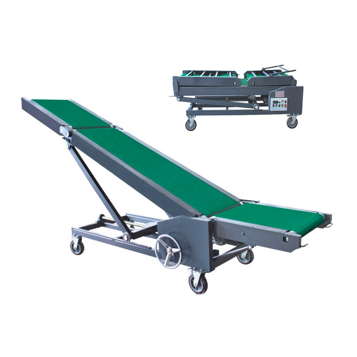
According to the type of main working parts, conveying equipment can be divided into: chain conveying equipment, belt conveying equipment, pneumatic conveying equipment, spiral conveying equipment and so on.
Among all these conveying equipment, chain conveying equipment has a wide range of specifications and is the most widely used.
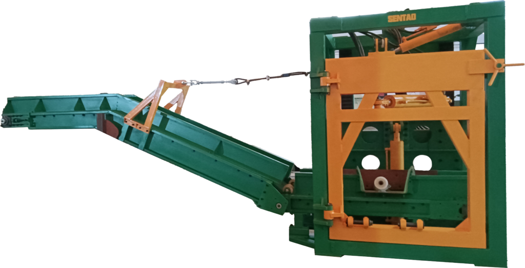
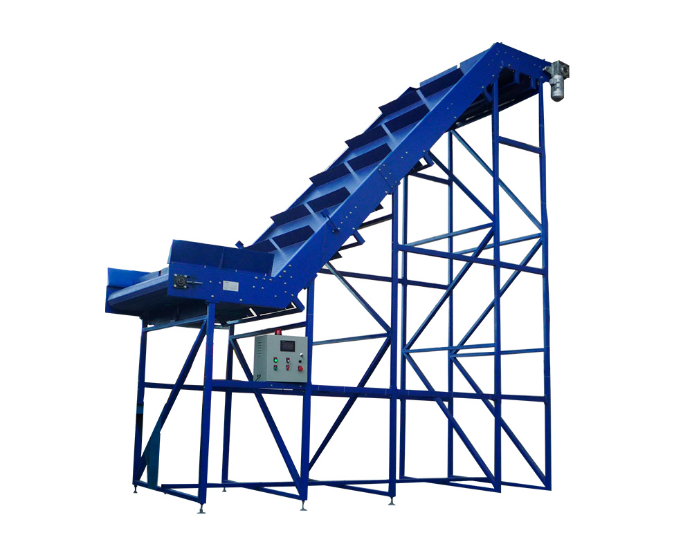
1-Drive unit
Chain conveyors generally do not run at high speed, but have high transmission torque and high transmission power. Therefore, the drive unit usually consists of a motor reduction unit. The drive unit rotates the drive shaft of the conveyor to realize the operation of the conveyor chain and the conveyance of the object.
The drive shaft is generally supported by a double-row spherical ball bearing seat (except for angle-driven suspension conveyor). Because the spherical ball bearing seat has the function of automatic centering, when the two supports have a certain amount of coaxiality error, it can ensure the normal work of the conveyor, and the double-row bearing ensures that it has sufficient bearing capacity.
The coupling of spindle and sprocket adopts key coupling. The traditional form of safety protection device is safety pin, which is broken when overload, but it is time-consuming and laborious to recover.
At present, the more advanced safety protection device is to set a flexible base and equipped with electrical travel switch, when the output torque of the reducer overload, the flexible base touches the electrical travel switch, the electrical travel switch acts to make the main motor timely power failure, when the fault is removed, it can automatically reset.
When the total length of the equipment is long and the load is large, and the chain tension will be too large if one drive device is used, an auxiliary drive device can be set in the middle of the equipment, and the two drives can be connected by a hydraulic coupling.
When the load exceeds the capacity of the main drive, the auxiliary drive will start. When the load is within the capacity of the main drive, the auxiliary drive automatically stops. Due to the difference of motor characteristics, it is impossible to ensure that the two motors have the same speed, so it is necessary not to design two drives to work at the same time for a long time, so that the output speed of the two drives is different and the chain will not produce additional tension (such as the drive of long-distance suspension conveyor usually adopts this structure); when designing the drive, the traction force, torque and power must be calculated, and according to the calculation results The motor, reducer, frequency converter, chain, support bearing seat, drive shaft and safety protection device must be correctly selected according to the calculation results.
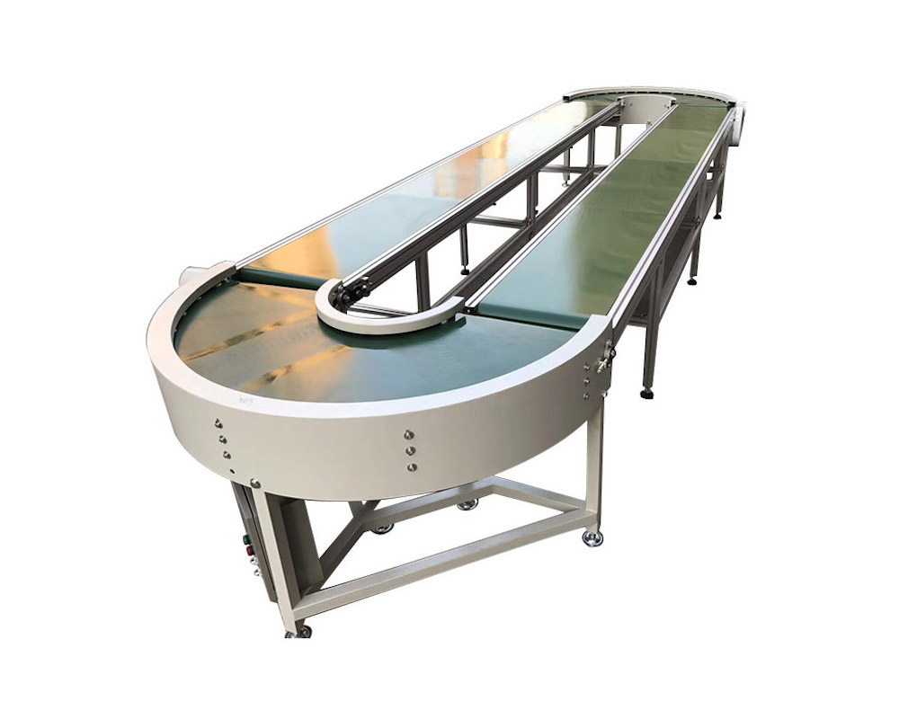
2-Tensioning device
The chain conveying equipment uses chain as the main body of the load, because the allowable length error of the chain is large, and the chain pitch will be elongated due to chain wear in the process of use. Therefore, the chain conveyor must be designed with tensioning device.
The tensioning stroke of the tensioning device is related to the working chain pitch and the length of the conveying line. The design principle of the tensioning amount is to meet the chain length tolerance and allow the chain wear to elongate two chain lengths, so as to ensure that the conveyor can work normally after removing two chains after the chain wear grows, so as to increase its service life.
The structure of tensioning device includes spiral tensioning structure (such as flat plate or scale plate conveyor), spring tensioning mechanism and heavy hammer tensioning mechanism (such as suspension conveyor).
As the chain tension of chain conveyors is usually large, when using spiral tensioning structure, attention must be paid to make the tensioning screw bear compressive stress, but not tensile stress, in order to meet the requirements of its strength and stiffness, especially when the shaft support seat of tensioning mechanism is cast iron.
The shaft support generally uses a double-row spherical ball bearing with sliding seat, the choice of this structure of the bearing seat, one is that it can move on the tensioning track to meet the requirements of tensioning, while the spherical bearing can ensure that when the two bearings have a certain amount of coaxiality error when the conveyor can work properly.
When the conveyor adopts double chains or more than two chains structure, because the length of each chain is not as long, the combination of the sprocket on the driven shaft and the shaft must not use the key connection, but should make the sprocket swim on the shaft to reduce the additional tension on the chain.
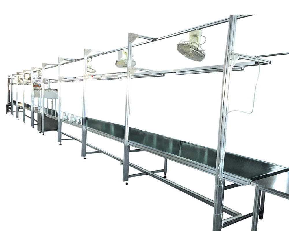
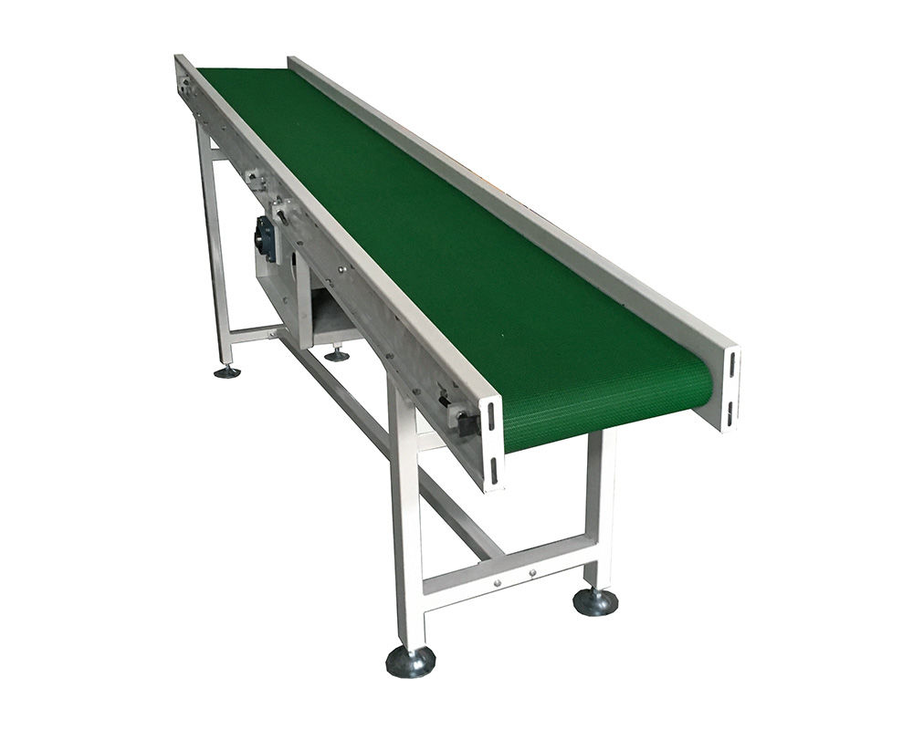
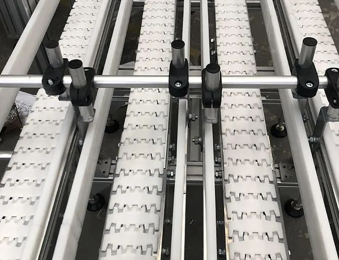
3-The main part of conveyor line
The frame is usually made of welded steel. The chain is the main working part of the chain conveying equipment, and the chain is a flexible structural part, so the bearing part of the chain must be supported by the supporting track, so that the chain can be carried as a rigid structure; when there is a sagging chain loose edge on the structure, in order to reduce the loose edge tension, improve the chain life and reduce the power capacity of the driving device, and to avoid the interference between the chain and the frame during the operation, the chain should be connected to the frame. The supporting track must be designed to avoid the interference between the chain and the frame in the process; the supporting track is often made of wear-resistant and anti-wear materials with certain strength.
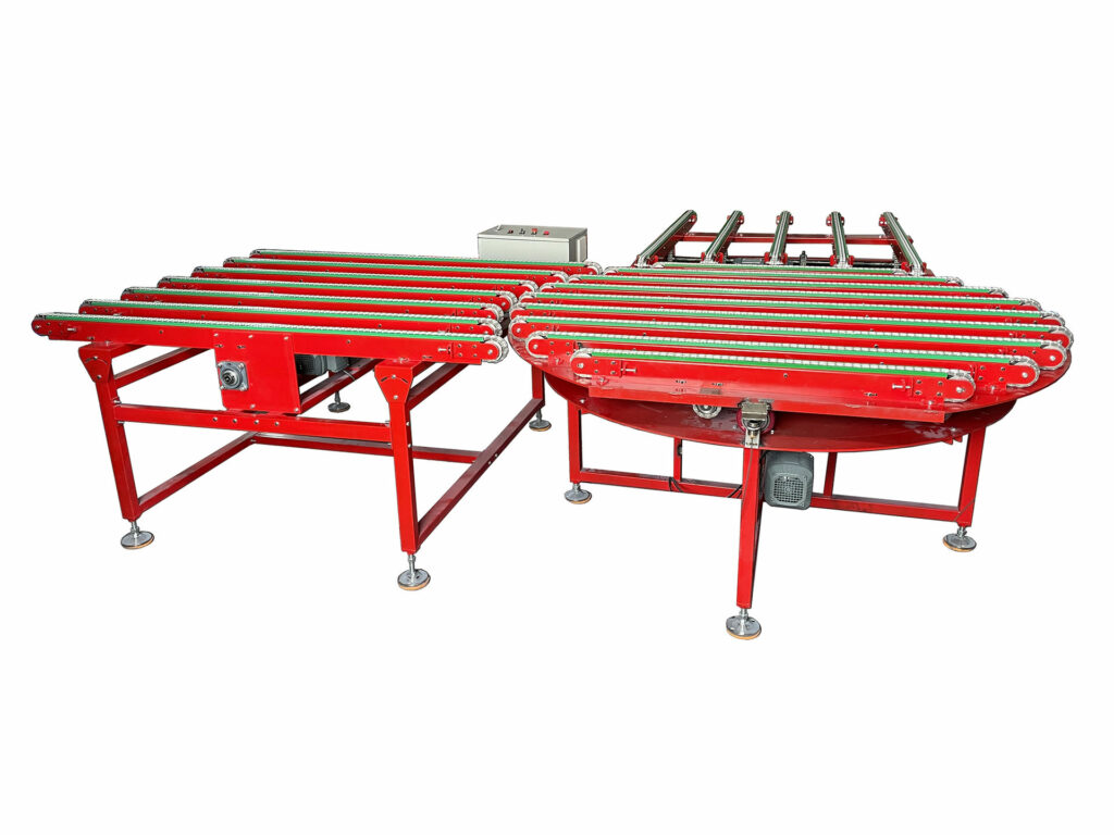
As the chain drive has polygon effect, when the structure needs to use chain drive step by step (such as power roller line), the number of teeth of the sprocket between levels should be the same, so that the transmission ratio between them is 1, so as to avoid the crawling phenomenon. When the equipment is a combination of two pieces of equipment with approximately the same structure, the two pieces of equipment should be driven by their own drive devices, do not drive the two pieces of equipment with one drive device, so as to avoid the polygon effect of the chain, so that the operation of the equipment appears obvious crawling phenomenon (such as the high and low line of the bridge-type automobile assembly line are driven by their own drive devices).
In order to meet the different production beats, the operation mode of the conveying equipment can be designed as synchronous and non-synchronous. Synchronous means that the conveying equipment runs at a certain speed within a certain speed range and according to a fixed beat, while non-synchronous means that the workpiece on the conveying equipment can be stopped and reset on the conveying line according to the requirements of the work station.
When the conveying method is non-synchronous, the structure of the stopping device and the release device after stopping is various, it can be purely mechanical or linked with gas or liquid and electric. No matter what structure form is used, the design should be reasonable, reliable and can meet the requirements of product assembly process, it is the difficult point of conveying equipment design and is the core technology.
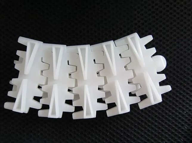
4-Selection of chain specification
For precision roller chain, the power curve is stipulated in the national standard. When designing, you can consult the mechanical design manual and select the chain specification according to the power curve according to the running speed and chain power transmission. Other forms of chain specifications are selected according to the empirical comparison method at this stage.
Nowadays, the general selection principle is that the breaking load of the chain is 5~7 times of the calculated load of the chain, and for the suspension chain, the breaking load of the chain is 7~10 times of the calculated load of the chain.
5-Electrical Control
In terms of electrical control, synchronous conveyor with simple work usually adopts conventional electrical control, whose control content mainly includes speed adjustment, drive protection, overload protection and limit protection.
Non-synchronous conveyors are generally controlled by PLC for process control, and computer control is selected when the functions of system grouping, addressing, transmission, protection and monitoring are included to make more control points. When a workshop has multiple conveyors to form an automatic production line, its control is more complicated than that of non-synchronous conveyors, and there are various management functions in addition to conveying workpieces, so computerized central program control is usually used.
In short, the control system of chain conveyor should depend on the specific working condition of the conveyor.
Chain conveyors have a wide range of structural forms, each with its own special characteristics. The control system should be adapted to the function of the assembly line, which is the main technical problem to be solved; the design and selection of reducer, motor, chain, bearing seat, etc., and the calculation of the strength check of the main and driven shaft are the main work in the design; the drive device, driven device and the main structure of the conveyor line are the core of the conveyor equipment; the chain is the key component of the assembly line.